

LDraw.org Library Requirements: General
- XXXX-XX-XX: Original
This is an ratified, official LDraw.org document. Non-adminstrative changes can only be made with the approval of the maintainer.
Introduction
The purpose of this document is to describe the requirements for files to be included in the LDraw.org Parts Library.
All requirements will be listed:
in block quote boxes
Text not in a block quote box is intended explain or otherwise provide context to the requirement.
Please Note:
These requirements have evolved over time, and there may be files in the LDraw.org Parts Library that do not conform to these requirements. These parts are not required to be edited solely for the purpose of bringing them into compliance. However, all parts currently on the Parts Tracker must meet current requirements including any fixes/changes to official parts.
General
These requirements apply to all file classes in LDraw.org Parts Library
In addition to the requirements listed in this document, all files in the LDraw.org Parts Library must conform to the LDraw File Format 1.0.2 specification.
File Names
Filenames must not be longer than 60 characters (including the extension) and must only contain the following characters:
a-z, 0-9, _,-
(To avoid confusion with English grammar, comma is not a permitted character.)
LDraw files are case-insensitive. However, all official parts will be issued with lower-case only file names.
Extension and Encoding
Text files will be encoded per the LDraw File Format and have a `.dat’ extension.
Image files will have a valid PNG encoding and a `.png’ extension.
Numbers
Precision
Four decimal places (at a minimum) shall be used for high-res primitives and any other file that is designed to be scaled (for example, cylinder sections, boxes, rectangles, discs, edges, etc.)
This allows such primitives to be scaled by a factor of ten while still preserving three decimal places of accuracy. The primitives reference indicates which primitive families are not designed to be scaled.
For all other files, three decimal places are sufficient.
Format
Trailing zeros must be removed (i.e. 1.5, not 1.500).
Leading zeros unless immediately before the decimal point must be removed (i.e. 1.5, not 01.5).
The leading zero before the decimal point is optional (i.e. 0.5 and .5 are both valid).
Geometry
Rotation Matrix
The matrix specified in line type 1 must not be singular nor contain columns or rows of all zeros.
Co-planar/Co-linear Tolerance and Concave Quads
Quads and triangles with co-linear vertices, quads with non-co-planer vertices are disallowed per the LDraw File Format. However, the tolerances for this co-linearity, co-planarity are not defined.
Every interior angle in a quad or triangle must not be greater than 179.9 degrees or smaller than 0.025 degrees.
A quad is considered co-planar if it is split into two triangles and both triangles are co-planar with each other. There are two ways to split a quad into two triangles, and both must result in co-planar triangles.
The triangles are considered co-planar if the angle between their surface normals is less than or equal to 3 degrees. However, an angle of less than 1 degree is required unless justification is given by the part author.
This is especially true for large quads where the "warp" can be seen at normal viewing magnifications.
Overlapping and Intersecting Line Types
All or part of a line (line type 2) may not overlap all or part of any other line (line type 2).
All or part of a conditional line (line type 5) may not overlap all or part of any other conditional line (line type 5), apart from complementary conditional lines for curved primitives.
Complementary conditional lines are placed at the end of curved primitives where those curved primitives may join with either a continuation of the curve, or with other geometry. In this case, the control points that are off of the edge of the curved primitive are placed so they are tangent to the curve.
If two such curves are placed next to each other (for example to turn a quarter cylinder into a half cylinder), the conditional lines on the edge of each primitive will overlap exactly, and their control points will complement each other such that at most one will be rendered at any given time, and one of the two will always be rendered when appropriate. When other geometry is placed against such a curved primitive, nothing needs to be done.
If the geometry is tangent to the curve. If it is sloped further, then a complementary conditional line shall be placed on the edge of that geometry, with the control points past the edge of the geometry configured to be tangent to the curve, and the two end points of the conditional placed to exactly overlap the complementary conditional line on the edge of the curved primitive.
Example:
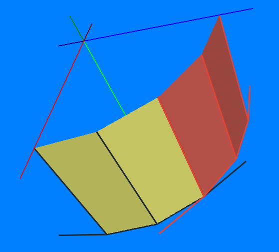
The first and last conditional lines in a cyli primitive have a control point that is tangent to the cylinder. When two such cyli primitives join, the two conditional lines complement each other, like so:
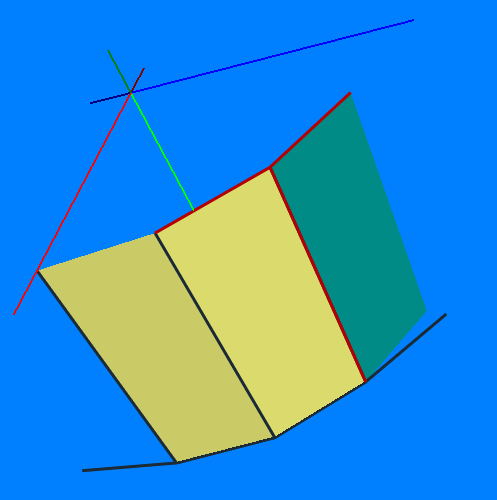
This shows the extra complementary conditional line an author is required to add if a surface is not placed in the tangential plane.
Part (but not all) of a conditional line (line type 5) may overlap all (but not part) of a line (line type 2). Consider the line A-B-C-D
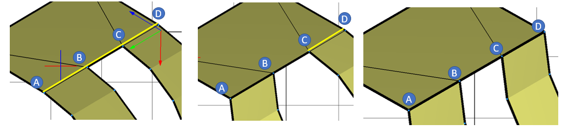
- If AB and CD need to be conditional lines and BC a line, it is acceptable to define this as a line BC and a single conditional line AD
- If AC needs to be a line and just CD needs to be a conditional line, it is not acceptable to define the conditional line as either AD or BD
- If AD is a line, there are no valid conditional lines along the length of AD
Lines (line type 2 or 5) may intersect any other line (line type 2 or 5).
Every effort must be made to remove overlapping co-planar polygons (line type 3 or 4). Where overlapping polygons are unavoidable, the overlap must be kept to the absolute minimum.
Every effort must be made to remove intersecting (non co-planar) polygons (line type 3 or 4). Where intersecting polygons are unavoidable, the intersection(s) must be kept to the absolute minimum.
Note: Primitives that overlap/intersect other primitives or polygons (line type 3 or 4), provided that the overlap is small, are considered acceptable. The intention is not to force part authors to in-line primitives. However, there may be some cases where it is better to use (say) a 3-8cyli and a quad than a 1-2cyli; case-by-case decisions are left to the parts review process.
Orientation/Origin
In general, parts that have studs should be oriented such that the top studs point up (-y) and the bottom tubes point down (+y).
For parts with studs, the origin of the parts will be the centered on the top most stud group. The bottom of studs should lie on the x-z plane (i.e. the bottom of the studs should be at y=0)
For hinge or hinge like parts, the origin should be at the rotation point**
These rules are generic. Look at other similar parts if it is unclear and if uncertainty remains, ask. If some other orientation/origin makes sense, the reasoning should be made when the part is submitted to the Parts Tracker.
Stud Orientation
The individual studs on a part should be rotated such that the stud logo appears is it would on the real part.
Since the generic stud.dat does not show a logo, rotation should be checked by using a LDraw program designed to show logo.
Subparts that use studs should not be mirrored as this would cause the logo to appear mirrored.
In this case, the studs can be moved from the subfile to the parent file which will avoid mirroring but still allow reuse of symmetrical geometry.
Duplicate Lines
Identical line type 1-5 lines are not permitted
The ordering of the vertex points in lines, quads, triangles, and conditional lines (line types 2-5) are not considered when checking for identical lines. The control points are not considered when checking for identical conditional lines (line type 5)
Colours
Colours are defined in the LDConfig.ldr file
Line types 1, 3 and 4 shall not use colour 24.
Line types 2 and 5 must use colour 24.
All colour numbers used in part files must be present in LDConfig.ldr, with the exception of pattern/sticker geometry, which may use Direct Colours (see LDraw File Format Spec).
LDConfig.ldr will only contain colours that have at some point in time been used by LEGO as the non-painted colour of materials used in LEGO-branded toys, plus ldraw.exe's special colour codes 16 and 24. This includes materials such as the metal track for 9V train tracks, but does not include the colours of paint used to decorate parts or ink used on stickers.
In general, metallic colours on stickers, patterned parts, and other printed materials should use the LDraw Metallic Colours and not Chrome or Pearl colours.
META Commands
Header Meta Commands
Official parts must conform to the Official Library Header Specification.**
Body Meta Commands
Only the following meta commands are permitted in the body of official parts:
- 0 // style comments
- All meta commands specified in Language Extension for Back Face Culling (BFC)
- All meta commands specified in Texture Mapping (!TEXMAP) Language Extension
Back Face Culling (BFC
All official parts will contain
0 BFC CERTIFY CCWand have valid corresponing winding on all quads and triangles
See Language Extension for Back Face Culling (BFC) for reference.
!TEXMAP
Sufficient !TEXMAP <geometry2> and/or <geometry3> lines (as outlined in the Texture Mapping (!TEXMAP) Language Extension) must be included such that the part renders correctly in non-!TEXMAP supporting programs.
A fallback pattern, if defined, must represent the pattern created by the TEXMAP image.
It is highly encouraged, but not required, that a fallback pattern be defined even if it is reduced in resolution or colors.
Generated File Meta Commands
Meta commands used by programs to generate file geometry may be left in the part file provided they are correctly commented out.
It is desirable to add a comment to mark the end of the generated section.
Website copyright ©2003-2025 LDraw.org, see Legal Info for details.
LDraw is a completely unofficial, community run free CAD system which represents official parts produced by the LEGO company.
LDraw™ is a trademark owned and licensed by the Estate of James Jessiman
LEGO® is a registered trademark of the LEGO Group, which does not sponsor,
endorse, or authorize this site. Visit the official Lego website at
http://www.lego.com